Thursday, November 20, 2008

Jet Propulsion Part 2

Turboprop

The turboprop is similar to the turbojet, except that most of the nozzle gas pressure drives the turbine shaft -- by the time the gas gets past the turbine, there's very little pressure left to create thrust.
Instead, the shaft is geared to a propeller which creates the majority of the thrust. 'Jet' helicopters work the same way, except that their engines are connected to the main rotor shaft instead of a propeller.

Turboprops are more fuel efficient than turbojets at low altitudes, where the thicker air gives a propeller a lot more 'traction.' This makes them popular on planes used for short flights, where the time spent at low altitudes represents a greater percentage of the overall flight time.

Turbofan

The turbofan is something like a compromise between a pure turbojet and a turboprop. It works like the turbojet, except that the turbine shaft also drives an external fan, usually located at the front of the engine.
The fan has more blades than a propeller and spins much faster. It also features a shroud around its perimeter, which helps to capture and focus the air flowing through it. These features enable the fan to generate some thrust at high altitudes, where a propeller would be ineffective.

Much of the thrust still comes from the exhaust jet, but the addition of the fan makes the engine more fuel efficient than a pure turbojet. Most modern jetliners now feature turbofan engines.

Jet Propulsion Part 1

Rocket
The rocket engine is the simplest of this family. In order to work in outer space, rocket engines must carry their own supply of oxygen as well as fuel. The mixture is injected into the combustion chamber where it burns continuously. The high-pressure gas escapes through the nozzle, causing thrust in the opposite direction.

Turbojet

The turbojet employs the same principle as the rocket. It burns oxygen from the atmosphere instead of carrying a supply along.
Notice the similarities: Fuel continuously burns inside a combustion chamber just like the rocket. The expanding gasses escape out the nozzle generating thrust in the opposite direction.
Now the differences: On its way out the nozzle, some of the gas pressure is used to drive a turbine. A turbine is a series of rotors or fans connected to a single shaft. Between each pair of rotors is a stator -- something like a stationary fan. The stators realign the gas flow to most effectively direct it toward the blades of the next rotor.
At the front of the engine, the turbine shaft drives a compressor. The compressor works a lot like the turbine only in reverse. Its purpose is to draw air into the engine and pressurize it.
Turbojet engines are most efficient at high altitudes, where the thin air renders propellers almost useless.

Gnome

The Gnome was one of several rotary engines popular on fighter planes during World War I. In this type of engine, the crankshaft is mounted on the airplane, while the crankcase and cylinders rotate with the propeller.
The Gnome was unique in that the intake valves were located within the pistons. Otherwise, this engine used the familiar Otto four stroke cycle. At any given point, each of the cylinders is in a different phase of the cycle. In the following discussion, follow the master cylinder with the green connecting rod.

During this portion of the stroke, a vacuum forms in the cylinder, forcing the intake valve open and drawing the fuel-air mixture in from the crankcase.
The mixture is compressed during this phase. The spark plug fires toward the end of the compression stroke, slightly before top dead center.
The power stroke happens here. Note that the exhaust valve opens early -- well before bottom dead center.
This engine has a fairly long exhaust stroke. In order to improve power or efficiency, engine valve timing often varies from what one might expect.
When I first learned how these engines worked, I thought the only person crazier than the engine designer was the one who paid money for it. At first glance it seems ridiculously backwards.

Nonetheless, a number of engines were designed this way, including the Gnome, Gnome Monosoupape, LeRhone, Clerget, and Bentley to name a few. It turns out there were some good reasons for the configuration:


Balance. Note that the crankcase and cylinders revolve in one circle, while the pistons revolve in another, offset circle. Relative to the engine mounting point, there are no reciprocating parts. This means there's no need for a heavy counterbalance.

Air Cooling. Keeping an engine cool was an ongoing challenge for early engine designers. Many resorted to heavy water cooling systems. Air cooling was quite adequate on rotary engines, since the cylinders are always in motion.

No flywheel. The crankcase and cylinders provided more than adequate momentum to smooth out the power pulses, eliminating the need for a heavy flywheel.


All these factors gave rotary engines the best power-to-weight ratio of any configuration at the time, making them ideal for use in fighter planes. Of course, there were disadvantages as well:


Gyroscopic effect. A heavy spinning object resists efforts to disturb its orientation (A toy gyroscope demonstrates the effect nicely). This made the aircraft difficult to maneuver.

Total Loss Oil system. Centrifugal force throws lubricating oil out after its first trip through the engine. It was usually castor oil that could be readily combined with the fuel. (The romantic-looking scarf the pilot wore was actually a towel used to wipe the slimy stuff off his goggles!)

The aircraft's range was thus limited by the amount of oil it could carry as well as fuel. Most conventional engines continuously re-circulate a relatively small supply of oil.

Atkinson Engine

The Atkinson engine is essentially an Otto-cycle engine with a different means of linking the piston to the crankshaft. It was originally designed to compete with the Otto engine, but without infringing on any of Otto's patents.
The clever arrangement of levers allows the Atkinson to cycle the piston through all four strokes in only one revolution of the main crankshaft, and allows the strokes to be different lengths -- the intake and exhaust strokes are longer than the compression and power strokes (In this illustration... see below).

This also obviates the need for a separate cam shaft. The intake (if used), exhaust, and ignition cams are located on the main crank shaft. My illustration shows only an exhaust cam.

Everything I know about the Atkinson engine came out of Building the Atkinson cycle Engine. This illustration draws heavily from that excellent book.

Wankel Engine

The Wankel radial engine is a fascinating beast that features a very clever rearrangment of the four elements of the Otto cycle. It was developed by Felix Wankel in the 1950s.1

In the Wankel a triangular rotor incorporating a central ring gear is driven around a fixed pinion within an oblong chamber.

The fuel/air mixture is drawn in the intake port during this phase of the rotation.
The mixture is compressed here.
The mixture burns here, driving the rotor around.
And the exhaust is expelled here.
The rotory motion is transferred to the drive shaft via an eccentric wheel (illustrated in blue) that rides in a matching bearing in the rotor. The drive shaft rotates once during every power stroke instead of twice as in the Otto cycle.

The Wankel promised higher power output with fewer moving parts than the Otto cycle engine, however technical difficulties have apparently interfered with widespread adoption. In spite of valiant efforts by Mazda, the four stroke engine remains much more popular.

Two Stroke Engine

The two stroke engine employs the crankcase as well as the cylinder to achieve all the elements of the Otto cycle in only two strokes of the piston.

Intake. The fuel/air mixture is first drawn into the crankcase by the vacuum created during the upward stroke of the piston. The illustrated engine features a poppet intake valve, however many engines use a rotary value incorporated into the crankshaft.
During the downward stroke the poppet valve is forced closed by the increased crankcase pressure. The fuel mixture is then compressed in the crankcase during the remainder of the stroke.
Transfer/Exhaust. Toward the end of the stroke, the piston exposes the intake port, allowing the compressed fuel/air mixture in the crankcase to escape around the piston into the main cylinder. This expels the exhaust gasses out the exhaust port, usually located on the opposite side of the cylinder. Unfortunately, some of the fresh fuel mixture is usually expelled as well.
Compression. The piston then rises, driven by flywheel momentum, and compresses the fuel mixture. (At the same time, another intake stroke is happening beneath the piston).

Power. At the top of the stroke the spark plug ignites the fuel mixture. The burning fuel expands, driving the piston downward, to complete the cycle.
Since the two stroke engine fires on every revolution of the crankshaft, a two stroke engine is usually more powerful than a four stroke engine of equivalent size. This, coupled with their lighter, simpler construction, makes two stroke engines popular in chainsaws, line trimmers, outboard motors, snowmobiles, jet-skis, light motorcycles, and model airplanes. Unfortunately most two stroke engines are inefficient and are terrible polluters due to the amount of unspent fuel that escapes through the exhaust port.

Four Stroke Engine

The four stroke engine was first demonstrated by Nikolaus Otto in 18761, hence it is also known as the Otto cycle. The technically correct term is actually four stroke cycle. The four stroke engine is probably the most common engine type nowadays. It powers almost all cars and trucks.


The four strokes of the cycle are intake, compression, power, and exhaust. Each corresponds to one full stroke of the piston, therefore the complete cycle requires two revolutions of the crankshaft to complete.

Intake. During the intake stroke, the piston moves downward, drawing a fresh charge of vaporized fuel/air mixture. The illustrated engine features a 'poppet' intake valve which is drawn open by the vacuum produced by the intake stroke. Some early engines worked this way, however most modern engines incorporate an extra cam/lifter arrangement as seen on the exhaust valve. The exhaust valve is held shut by a spring (not illustrated here).
Compression. As the piston rises the poppet valve is forced shut by the increased cylinder pressure. Flywheel momentum drives the piston upward, compressing the fuel/air mixture.
Power. At the top of the compression stroke the spark plug fires, igniting the compressed fuel. As the fuel burns it expands, driving the piston downward.
Exhaust. At the bottom of the power stroke, the exhaust valve is opened by the cam/lifter mechanism. The upward stroke of the piston drives the exhausted fuel out of the cylinder.
This animation also illustrates a simple ignition system using breaker points, coil, condenser, and battery.

Larger four stroke engines usually include more than one cylinder, have various arrangements for the camshaft (dual, overhead, etc.), sometimes feature fuel injection, turbochargers, multiple valves, etc. None of these enhancements changes the basic operation of the engine.

Tuesday, May 06, 2008

SIKLUS MESIN 4-TAK (Bagian Sepuluh)

RELASI EFISIENSI TERMAL DAN RASIO KOMPRESI


Merujuk kpd uraian sebelumnya diatas, krn

TE = [1 - (T4 - T1) / (T3 - T2)] x 100%

dan

CR = V2 / V1 = (T3 - T2) / (T4 - T1)

shg

TE = (1 - 1 / CR) x 100%


Seluruh formulasi dan kalkulasi diatas menggunakan aproksimasi ideal dimana panas jenis (spesific heat) dianggap bernilai smdgn 2.

Jika, panas jenis diperhitungkan, maka formula efisiensi termal real menjadi

TE = [1 - 1 / CR^(h-1)] x 100%

dimana h adalah panas jenis gas campuran udara dan bahanbakar, yg mana utk nilai h = 2,

TE = (1 - 1 / CR) x 100%

Jika CR = 9 dan h = 1,5 [utk udara, nilai h mendekati 1,4], maka

TEi = (1 - 1 / 9) x 100% = 0,889 x 100% = 88,9%
TEr = [1 - 1 / [9^(1,5 - 1)]] x 100% = (1 - 1 / 9^0,5) x 100% = (1 - 1/3) x 100% = (1 - 0,333) x 100% = 0,666 x 100% = 66,6%

Rasio kompresi mesin Suzuki Thunder, berdasarkan data spesifikasi teknik, adalah 9,2, berarti efisiensi termal mesin Suzuki Thunder adalah

TEi = (1 - 1/9,2) x 100% = 0,891 x 100% = 89,1%
TEr = [1 - 1 / [9.2^(1,5 - 1)]] x 100% = (1 - 1 / 9.2^0,5) x 100% = (1 - 1/3,033) x 100% = (1 - 0,33) = 0,67 x 100% = 67%

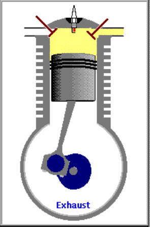
Kembali pd pernyataan pertama diatas bahwa hampir seluruh kalkulasi diatas menggunakan aproksimasi ideal, namun dlm kenyataan, pd mesin pembakaran dalam 4-tak dgn bahanbakar bensin, banyak faktor lain mesin yg mempengaruhi keseluruhan proses, shg menurunkan efisiesi termal mesin, al.

* 1. dinding silinder adalah bukan metal ideal, shg ada tenaga panas hilang krn penyerapan panas oleh metal dinding silinder.
* 2. gesekan|friksi antara bagian2 mesin tdk nol krn mesin menggunakan oli | minyak pelumas bukan ideal shg tak ada tenaga gerak hilang utk mengatasi gesekan.
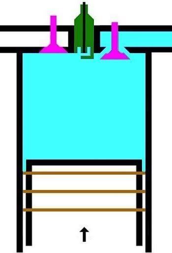
* 3. udara yg memasuki silinder mesin, tak berlaku sbg gas ideal yg memiliki kapasitas panas tetap, dimana panas jenis (specific heat) 1,4, dan dimana gas campuran udara dan bahanbakar dlm silinder mengalami turbulensi|gejolak.
* 4. mesin, dlm prakteknya, tak selalu dlm status "idle", tanpa beban, kendaraan tak diam alias bergerak, shg ada akselerasi|percepatan dan dekselerasi|perlambatan dlm gerak mesin, shg seluruh proses adalah tak "quasi-static" alias berlangsung dgn perubahan labil.


Jadi, dlm praktek, secara teknis, mesin dgn efisiensi antara 60% s/d 70% sdh dianggap cukup efisien, atau memiliki efisiensi normal.

Efisiensi termal mesin dpt ditingkatkan dgn bbrp cara,al.

* 1. meningkatkan rasio kompresi antara 9 dan 10 [hrs turun mesin].
* 2. meningkatkan suhu penyalaan dan pembakaran via peningkatan tegangan elektroda busi, dgn cara menambahkan SPB (spark-plug booster) antara koil dan busi, dan mengganti busi dgn yg lbh tahan panas.
* 3. meniadakan endapan kerak arang|karbon dlm ruang silinder mesin, dgn cara meningkatkan pembakaran menjadi lbh sempurna, al via cara 2.
* 4. melapisi permukaan metal mesin dgn bahan gel anti-friksi [minimasi friksi].
* 5. meningkatkan nilai kekentaan|viskositas oli | minyak pelumas, dgn mengganti pelumas dgn yg memiliki viskositas lbh kental pd suhu tinggi.
* 6. meningkatkan nilai oktan bahanbakar, shg tak terjadi pembakaran dini (pre-ignition) yg menimbulkan letupan (detonation) dan ketukan (knocking) pd mesin,
dgn cara mengganti bahanbakar dgn yg memiliki nilai oktan lbih tinggi [tapi tentu dgn harga lbh mahal].
* 7. melumasi dgn baik seluruh bagian bergerak | mekanisme kendaraan, dan memelihara agar tekanan angin ban selalu pd ukuran tepat [ini juga minimasi friksi].

SIKLUS MESIN 4-TAK (Bagian Sembilan)

FORMULASI DAN KALKULASI RASIO KOMPRESI MESIN


Merujuk kpd uraian sebelumnya diatas, dari relasi 6 fase termodinamik siklus Otto mesin 4-tak diatas, diperoleh bahwa

V2 / V1 = T2 / T1 = T3 / T4

dan juga bisa diperoleh bahwa

(T2 - T1) / T2 = (T3 - T4) / T3

atau

1 - T1/T2 = 1 - T4/T3

Nilai perbandingan V2 / V1 adalah rasio ekspansi|pemuaian (expansion ratio, XR, Rx) atau rasio kompresi|pemampatan (compression ratio, CR, Rc) isentropik volume silinder.

Berdasarkan dua relasi diatas diperoleh bahwa

CR = V2 / V1 = (T3 - T2) / (T4 - T1)

Dgn kata lain, rasio ekspansi atau rasio kompresi isentropik volume silinder adalah perbandingan volume total silinder dan volume kamar bakar (combustion chamber}, yg mana setara dgn perbandingan beda suhu pemampatan dan beda suhu pembuangan.

Utk lbh jelas, silahkan lihat kembali ilustrasi dlm diagram PVT.


Dlm kenyataan, pd mesin pembakaran dalam 4-tak dgn bahanbakar bensin, rasio kompresi tak dapat dibuat lbh besar drpd 10, krn jika rasio kompresi lbh besar drpd 10, maka peningkatan suhu dlm proses kompresi gas campuran udara dan bahanbakar akan dpt memanaskan dan membakar gas tsb sebelum gas tsb dibakar oleh percikan listrik busi, shg menimbulkan penyalaan dini (premature ignition) atau pra-penyalaan (pre-ignition) shg terjadi letupan (detonation) yg menimbulkan suara ketukan (knocking) dan gelitik (pinking) pd mesin.

SIKLUS MESIN 4-TAK (Bagian Delapan)

FORMULASI DAN KALKULASI EFISIENSI TERMAL VIA BEDA TEMPERATUR


Merujuk kpd uraian sebelumnya diatas, aliran tenaga panas masukan|input Q1 berlangsung selama proses pemanasan dan penyalaan dan pembakaran dalam garis T2-T3 dan tenaga panas keluaran|output Q2 berlangsung selama proses pendinginan dan pembuangan T4-T1.

Relasi termodinamik menunjukkan bahwa kuantitas tenaga panas Q1 dan Q2 memiliki hubungan langsung dengan suhu panas T2 dan T3 dan T4 dan T1, dimana kuantitas tenaga panas masukan|input Q1 dgn perubahan suhu pemanasan T2 dan T3, dan kuantitas tenaga panas keluaran|output Q2 dgn perubahan suhu pendingan T4 dan T1.

Proses pemasukan|pengambilan gas campuran bahanbakar dan udara dlm garis T0-T1, dan proses pengeluaran|pembuangan sisa gas pembakaran dlm garis T1-T0, bukan merupakan sistem tertutup termodinamik (thermodynamic closed system), tp sistem terbuka termodinamik (thermodynamic open system), shg bukan merupakan bagian inti dr konversi energi dlm siklus Otto yg merupakan sistem tertutup termodinamik. Dua proses ini mengambil tenaga|energi mesin shg mengurangi efisiensi.


Relasi termodinamik menunjukkan bahwa efisiensi termal (thermal efficiency TE, Et) siklus Otto dlm sistem ini adalah, persentasi perbandingan kuantitas tenaga mekanik keluaran (mechanical energy quantity output) dan kuantitas tenaga panas masukan (heat energy quantity input), yg bila dijabarkan secara matematik fisika adalah sbb.

TE = W / Q1 x 100% = [(Q1 - Q2) / Q2] x 100% = [1 - Q2 / Q1] x 100%

dimana jika W = Q1 atau Q2 = 0, maka efisiensi 100%.

Jika dinyatakan hubungan dalam suhu, maka

TE = [1 - (T4 - T1) / (T3 - T2)] x 100%

shg efisiensi termal setara dgn persentasi satu dikurangi perbandingan beda suhu pembuangan dan beda suhu pemampatan.

Tp ini adalah formula aproksimasi gas ideal. Utk gas real berlaku formula sbb.

TE = [1 - [(T4 - T1) / (T3 - T2)]^(h-1)] x 100%

dimana h adalah panas jenis gas campuran udara dan bahanbakar, yg mana utk nilah h = 2,

TE = [1 - (T4 - T1) / (T3 - T2)] x 100%


Sbg contoh, suhu pemasukan gas campuran bahanbakar dan udara T1 adalah sekitar 25 derajat, kemudian memanas selama kompresi menjadi T2 sekitar 230 C. Lalu ketika penyalaan dan pembakaran memanas menjadi T3 sekitar 644 C, dan kemudian mendingin selama pengeluaran menjadi T4 sekitar 70 C, sampai akhirnya kembali mencapai T1 sekitar 25 C.

Jadi, krn,

T1 = 25
T2 = 230
T3 = 644
T4 = 70

TEi = [1 - (70 - 25) / (644 - 230)] x 100% = [1 - 45 / 414] x 100% = [1 - 0,109] x 100% = 0,891 x 100% = 89,1%
TEr = [1 - [(70 - 25) / (644 - 230)]^0,5] x 100% = [1 - (45 / 414)^0,5] x 100% = [1 - 0,33] x 100% = 0,67 x 100% = 67%

dimana,

TEi = efisiensi termal ideal
TEr = efisiensi termal real

SIKLUS MESIN 4-TAK (Bagian Tujuh)

DISKUSI, FORMULASI DAN KALKULASI TERMODINAMIK


Merujuk kpd uraian sebelumnya diatas, sepasang proses isobarik T0-T1 dan T1-T0 adalah setara dan berlawanan arah, positiv dab negativ, shg secara matematik saling membatalkan satu thdp yg lain, alias hasilnya nol, shg tak perlu dilibatkan dlm perhitungan lbh lanjut. Sisanya adalah 4 proses pasangan adiabatik dan isokorik, namun hanya pasangan proses isokorik yg melibatkan penyerapan dan pelepasan tenaga panas, yakni penyerapan kuantitas tenaga panas Q1 antara T2-T3 dan pelepasan kuantitas tenaga panas Q2 antara T2-T1. Aliran panas (heat flow, heat transfer) sbg tenaga (energy) inilah yg menjadi obyek termodinamika.

Dengan asumsi bahwa kapasitas|tampungan panas adalah tetap (constant) sepanjang garis T2-T3, dan juga sepanjang garis T4-T1, diperoleh bahwa

Q1 = Ch x (T3 - T2)

Q2 = Ch x (T4 - T1)

dimana,

Q, kuantitas tenaga panas (quantity of heat energy, heat quantity).
Ch, kapasitas tenaga panas (capacity of heat energy, heat capacity).

shg diperoleh hubungan antara kuantitas tenaga panas dgn perubahan suhu,

Q2 / Q1 = T4 - T1 / T3 - T2

SIKLUS MESIN 4-TAK (Bagian Enam)

4. LANGKAH PEMBUANGAN|PENGELUARAN GAS [GARIS T4-T1 DAN GARIS T1-T0, T4 = 70 C, T1 = 25 C]


GARIS T4-T1, T4 = 70 C
4.A. Garis T4-T1 adalah garis fase proses isovolumik|isokorik quasi-statik termodimamik, menggambarkan proses pendinginan dan pengeluaran tenaga panas hasil pembakaran, ketika klep|katup keluar|buang membuka. Dlm proses ini, volume gas tetap pd V2, bobot gas campuran tetap m2, tekanan gas merosot turun dr P4 ke P1, shg suhu gas merosot turun dari T4 ke T1.

(P4 - P1) . V2 = m2 . R . (T4 - T1)

dimana gas sisa pembakaran didinginkan sampai mencapai tekanan dan suhu udara luar, shg tekanan dan suhu gas merosot sekitar 1/2,8 x lipat, 70 ke 25 derajat.

Dlm proses ini, klep|katup keluar|buang membuka, shg sistem melepaskan tenaga panas ke reservoir panas luar dgn suhu 25 C, yakni knalpot.


GARIS T1-T0, T1 = 25 C
4.B. Garis T1-T0 adalah garis fase proses isobarik quasi-statik ireversibel termodimamik, menggambarkan langkah pembuangan sisa pembakaran, piston naik, ruang silinder mengecil. Dlm proses isobarik quasi-statik ini, dimana tekanan gas P dan suhu gas T tetap dan setara tekanan atmosfir [udara luar] krn klep|katup keluar|buang terbuka. Volume silinder V mengecil dr V2 ke V1, shg bobot gas sisa pembakaran berkurang dr m2 ke m1.

P1 . (V2 - V1) = (m2 - m1) . R . T1

dimana gas sisa pembakaran mencapai tekanan dan suhu udara luar, dan dimana pada akhir proses volume dan molekul gas mendekati nol, pd tekanan dan suhu udara luar.

P1 . V1 = m1 . R . T1

Sampai disini 6 fase siklus Otto dlm siklus mesin 4-tak berakhir dan berulang kembali menjalani daur ulangnya.

SIKLUS MESIN 4-TAK (Bagian Lima)

3. LANGKAH PENYALAAN|PEMBAKARAN DAN PENDAYAAN|KONVERSI GAS [GARIS T2-T3 DAN KURVA T3-T4, T3 = 644 C DAN T4 = 70 C]


GARIS T2-T3, T3 = 644 C
3.A. Garis T2-T3 adalah garis fase proses isovolumik|isokorik quasi-statik termodimamik, menggambarkan proses pemanasan dan penyalaan dan pembakaran gas campuran bahanbakar dan udara oleh percikan busi, ketika pasangan klep|katup tertutup. Dlm proses ini, Volume gas tetap pd V1, tp krn pemanasan, tekanan gas meningkat naik dr P2 ke P3, shg suhu gas meningkat naik dari T2 ke T3.

(P3 - P2).V1 = m2 . R . (T3 - T2)

dimana gas dibakar, shg tekanan dan suhu gas meningkat sekitar 2,8 x lipat, dari 230 C ke 644 C.

Dlm proses ini, pasangan klep|katup dlm keadaan tertutup, shg tak ada gas masuk ke dan keluar dr silinder, tp silinder menyerap tenaga panas dr serangkaian reservoir panas luar dgn rangkum suhu panas dr T2 ke T3, yakni peledakan gas campuran bahanbakar dan udara oleh percikan listrik busi.


KURVA T3-T4, T4 = 70 C
3.B. Kurva T3-T4 adalah kurva fase proses adiabatik isentropik quasi-statik reversibel termodinamik, menggambarkan langkah pendayaan krn pembakaran gas campuran udara dan bahanbakar dlm silinder ketika pasangan klep|katup tertutup shg piston turun 180 derajat, ruang silinder membesar. Dlm proses adiabatik quasi-statik ini, volume silinder dan volume V membesar dr V1 ke V2, bobot gas campuran tetap m2, tekanan gas P merosot turun dr P3 ke P4, dan suhu gas T merosot turun dr T3 ke T4

(P3 - P4)(V2 - V1) = m2 . R . (T3 - T4)

dimana gas dimuaikan, shg tekanan dan suhu gas merosot sekitar 1/9,2 x lipat, dari 644 C ke 70 C.

Perubahan volume berbanding terbalik dgn perubahan suhu, krn volume membesar dan suhu merosot.

(V1 / V2)^(h-1) = T4 / T3

dimana h, panas jenis (spesific heat) gas campuran udara dan bahanbakar.

Utk aproksimasi ideal, h = 2, formula menjadi

V1 / V2 = T4 / T3

V1 . T3 = V2 . T4

SIKLUS MESIN 4-TAK (Bagian Empat)

2. LANGKAH PEMAMPATAN|KOMPRESI GAS [KURVA T1-T2, T2 = 230 C]


KURVA T1-T2, T2 = 230 C
Kurva T1-T2 adalah kurva fase proses adiabatik isentropik quasi-statik reversibel termodinamik, menggambarkan langkah pemampatan gas campuran udara dan bahanbakar dlm silinder ketika pasangan klep|katup tertutup dan piston naik 180 derajat, ruang silinder mengecil. Dlm proses ini, volume silinder dan volume gas V mengecil dr V1 ke V2, bobot molekul gas campuran bahanbakar dan udara tetap m2, tekanan gas P meningkat naik dr P1 ke P2, dan suhu gas T meningkat naik dr T1 ke T2

(P2 - P1).(V2 - V1) = m2.R.(T2 - T1)

dimana gas dimampatkan, shg tekanan dan suhu gas meningkat sekitar 9,2 x lipat, dari 25 C ke 230 C.

Perubahan volume berbanding terbalik dgn perubahan suhu, krn volume mengecil dan suhu meningkat.

(V1 / V2)^(h-1) = T1 / T2

dimana h, panas jenis (spesific heat) gas campuran udara dan bahanbakar.

Utk aproksimasi ideal, h = 2, formula menjadi

V1 / V2 = T1 / T2

V1 . T2 = V2 . T1

Monday, May 05, 2008

SIKLUS MESIN 4-TAK (Bagian Tiga)

1. LANGKAH PENGAMBILAN|PEMASUKAN | PENGISAPAN GAS [GARIS T0-T1, T1 = 25 C]


GARIS T0-T1, T1 = 25 C
Garis T0-T1 adalah garis fase proses isobarik-isotermik quasi-statik termodimamik, menggambarkan langkah pemasukan | pengambilan dan penyedotan gas campuran udara dan bahanbakar pd tekanan dan suhu tetap dr karburator ke silinder mesin, ketika klep|katup masuk|ambil membuka dan piston turun 180 derajat, ruang silinder membesar. Dlm proses ini, tekanan gas P dan suhu gas T, tetap dan setara tekanan dan suhu standar normal udara luar (normal standard atmospheric pressure and temperature), krn klep|katup masuk|ambil terbuka. Volume silinder V membesar dr V1 ke V2, shg bobot molekul gas campuran bahanbakar dan udara dlm silinder bertambah dr m1 ke m2.

P1 . (V2 - V1) = (m2 - m1). R . T1

P1 = P0 = Patm, tekanan atmosfir | udara luar
T1 = T0 = Tatm, suhu atmosfir | udara luar
m1 = mo = nol [ideal nol, praktis mendekati nol]

dimana suhu awal silinder setara suhu udara luar, sekitar 25 C.

Dlm proses ini, klep|katup masuk|ambil membuka, shg sistem menyerap tenaga panas dr reservoir panas luar dgn suhu 25 C, yakni karburator.

SIKLUS MESIN 4-TAK (Bagian Dua)

FORMULA DASAR TERMODINAMIK GAS IDEAL

Utk informasi anda saja, bagian ini mengandung batasan istilah (term definition) proses dlm termodinamika yg digunakan utk menjelaskan rangkaian proses berlangsung dlm mesin bakar bensin 4-tak, dan formula matematik fisika, dasar termodinamika, yd digunakan utk melakukan perhitungan teknik dan memperoleh kesimpulan.

Dlm sistem termodinamik ada bbrp istilah utk proses, yg dlm konteks ini, al sbb.

reversibel (reversible): proses bisa-dibalik, bisa-dikembalikan, bisa bolak-balik.
ireversibel (irreversible): proses tak bisa-dibalik.
quasi-statik (quasi-static): proses dgn statik infinitesimal, hampir statik, hampir stabil.
adiabatik (adiabatic): proses dgn aliran panas (heat flow) atau perpindahan panas (heat transfer), dimana efek kompresi adiabatik adalah pemanasan gas, dan sebaliknya, efek ekspansi adiabatik adalah pendinginan gas.
isentropik (isentropic): proses pd entropi tetap (constant entropy). Suatu proses adibatik reversibel adalah isentropik, dimana selama berlangsung perubahan adibatik, entropi tetap tak berubah.
isobarik (isobaric) atau isopiestik (isopiestic): proses pd tekanan tetap (constant pressure).
isotermik, isotermal (isothermic, isothermal): proses pd suhu tetap (constant temperature).
isovolumik, isovolumetrik (isovolumic, isovolumetric) atau isokorik (isochoric): proses pd volume tetap (constan volume).


Disini tak akan dibahas lbh lanjut ttg bbg istilah termodinamik ini, cukup hanya sbg pengetahuan dasar utk membedakan kelangsungan suatu proses termodinamik dlm mesin pembakaran dalam 4-tak dgn bahanbakar bensin akan dikupas secara rinci disini.


Berikut adalah formula dasar termodinamika.

Buat yg gerah dgn matematika, cukup sbg pengetahuan saja, dan silahkan lewatkan, dan lihat ringkasan dan kesimpulan pd bagian akhir.


Sistem termodinamik adalah merupakan fungsi 4-dimensional dlm suatu sistem tertutup,

f (P, V, T, m) = 0

dengan formula dasar keseimbangan termodinamik (themodynamic equilibrium)

P . V = m . R . T

dimana,

p = pressure (tekanan, desakan), dlm unit Pa (Pascal) atau N/m2 (Newton per square metre).
T = temperature (suhu), dlm unit K (Kelvin) atau C (Celcius, Centigrade).
V = volume (isi, kandungan), dlm unit m3 (cubic metre).
m = mass (masa, bobot), dlm unit kg (kilogramme).
R = universal gas constant (konstanta gas universal), dlm unit Pa.m3/kg.K.

Unit|satuan ukuran digunakan disini adalah unit sistem internasional (SI unit, systeme international d'unites). Dlm rekayasa termodinamik (thermodynamic engineering) digunakan satuan rekayasa Inggris (British engineering unit). Dlm uraian ini tak dibahas lbh jauh ttg unit ukuran, dan diluar cakupan tulisan ini.

Jika kandungan panas jenis gas diperhitungkan, maka formula diatas menjadi

P . V^h = m . R . T = K

dan

h = cp / cv
R = cp - cv, utk gas ideal.

dimana,

h = panas jenis (specific heat) gas, rasio tampungan|kapasitas panas jenis gas.
c = tampungan|kapasitas panas jenis (specific heat capacity) gas.
cp= c pd tekanan tetap; kapasitas panas jenis isobarik.
cv= c pd volume tetap; kapasitas panas jenis isovolumik.
C = tampungan|kapasitas panas (heat capacity, thermal capacity) gas, yakni kuantitas panas dibutuhkan utk meningkat 1 derajat suhu suatu gas.
K = tetapan|konstanta (constant).

Q = C . T
dQ = C . dT

dimana,

Q = kuantitas panas (quantity of heat, heat quantity).
dQ= perubahan kuantitas panas.
dT= perubahan suhu (temperature difference).

Q = S . T
dQ = dS . T

S = Q / T
dS = dQ /T

dimana,

S = entropi (entropy), ukuran relativ kuantitas energi tak-bisa-diperoleh dlm suatu sistem.
dS= perubahan entropi.

H = U P . V

dimana,

H = entalpi (enthalpy), kandungan panas (heat content).
U = tenaga internal (internal energy).


catatan penulisan:
tanda . atau * atau x berarti kali.
tanda ^ atau ** berarti pangkat (exponent).
tanda ^(1/2) atau **0,5 berarti pangkat setengah atau akar kuadrat (square root).

SIKLUS MESIN 4-TAK (source suzuki-thunder forum)

FASE TERMODINAMIK SIKLUS OTTO DALAM SIKLUS MESIN 4-TAK,
FORMULASI DAN KALKULASI RASIO KOMPRESI DAN EFISIENSI TERMAL MESIN,
DAN EFEK NUFTON SPB TERHADAP KINERJA MESIN


BAGIAN PERTAMA

Perilaku mesin bensin 4-tak dpt dijabarkan dlm termodinamika menggunakan formula matematika fisika sederhana.

Untuk menyederhanakan masalah dan memudahkan perhitungan, dilakuan pendekatan dgn pengandaian keadaan ideal, sbb.


1. dinding silinder adalah metal ideal, shg tak ada tenaga panas hilang krn penyerapan panas oleh metal dinding silinder.
2. gesekan|friksi antara bagian2 mesin dianggap nol atau mendekati nol krn mesin menggunakan oli | minyak pelumas ideal shg tak ada tenaga gerak hilang utk mengatasi gesekan.
3. udara yg memasuki silinder mesin, berlaku sbg gas ideal yg memiliki kapasitas panas tetap, dimana koeefisien panas jenis (specific heat) dianggap smdgn 2.
4 mesin dlm status "idle", tanpa beban, kendaraan diam, shg tak ada akselerasi|percepatan dan dekselerasi|perlambatan dlm gerak mesin, shg seluruh proses adalah "quasi-static" alias berlangsung dgn perubahan stabil penuh.


Dgn menggunakan semua asumsi diatas, siklus mesin 4-tak dpt dijabarkan dlm termodinamika sbg 6 fase siklus Otto standar-udara (air-standard Otto Cycle), yg terdiri dari 6 proses sederhana gas ideal, sbb.


1.X. pengambilan|pemasukan | penyedotan gas [campuran bahanbakar dan udara].
2.X. pemampatan|kompresi gas
3.A. pemanasan dan pembakaran gas
3.B. pendayaan|konversi gas, dr tenaga panas ke tenaga gerak.
4.A. pendinginan gas sisa pembakaran.
4.B. pembuangan|pengeluaran gas sisa pembakaran.

6 fase siklus Otto ini dpt digambarkan dlm diagram PVT (pressure, volume, temperature; tekanan, isi, suhu) 3-dimensi, atau diagram PV 2-dimensi sbb.


dimana, masing2 proses digambarkan dgn garis PVT atau kurva PVT.

1.X. garis. T0-T1
2.X. kurva T1-T2
3.A. garis. T2-T3
3.B. kurva T3-T4
4.A. garis. T4-T1
4.B. garis. T1-T0


Lihat gambar.